3D Annotation Tools
Updated at January 3rd, 2025
3D Cuboid
Cuboid points
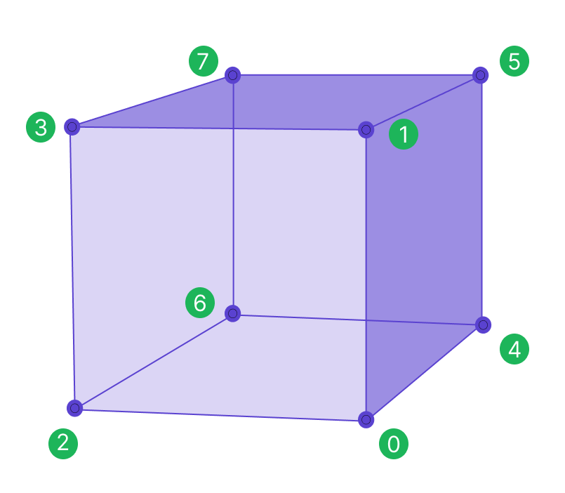
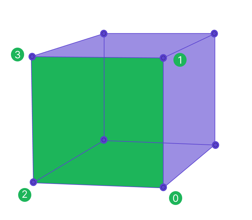
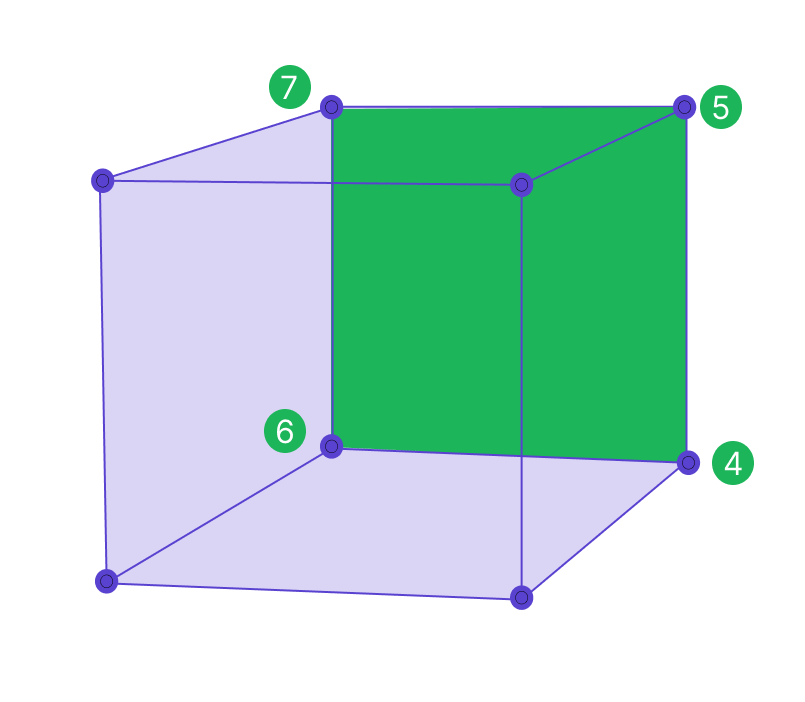
The (x,y,z) vertices of each cuboid always follow a pattern: one full face and then the other full face.
These faces may be “front” and “back,” “left” and “right,” or “top” and “bottom,” depending on the cuboid’s rotation.
Cuboid
 Face One
 Face Two
 |
Face of interest
The face of interest is defined by the first four vertices of the cuboid listed in the export file. A face of interest, or side of the cuboid, can be used to designate the front of a car or the direction of movement of an object bounded by a cuboid. Therefore, there is always a default face of interest.
Sama associates may change the default face to a new face of interest in the workspace if they are instructed to define a face of interest on a project. The data will always contain this information, but it will only be meaningful as a face of interest if workers are instructed to actively select a face of interest according to project instructions. In the diagram above, the side bounded by the labeled points 0,1,2,3 is the face of interest.
📘Note
The cuboid vertex export order can be used to define a face of interest.
Cuboid dimensions
Center
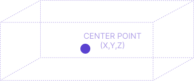
The position_center (x,y,z) is the center point of the cuboid
Length
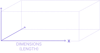
The cuboid length goes along the x-axis
Width
The cuboid width goes along the y-axis
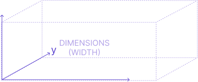
Height
The cuboid height goes along the z-axis

Cuboid Direction
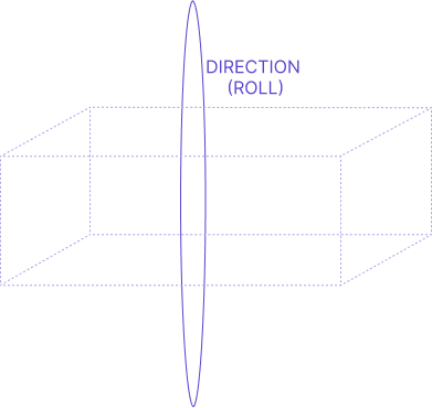
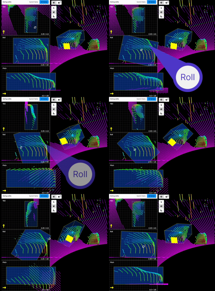
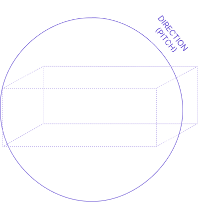
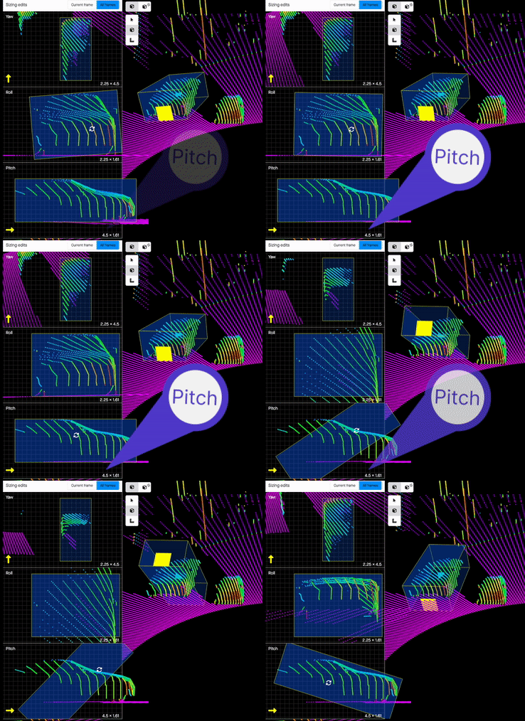
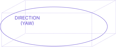
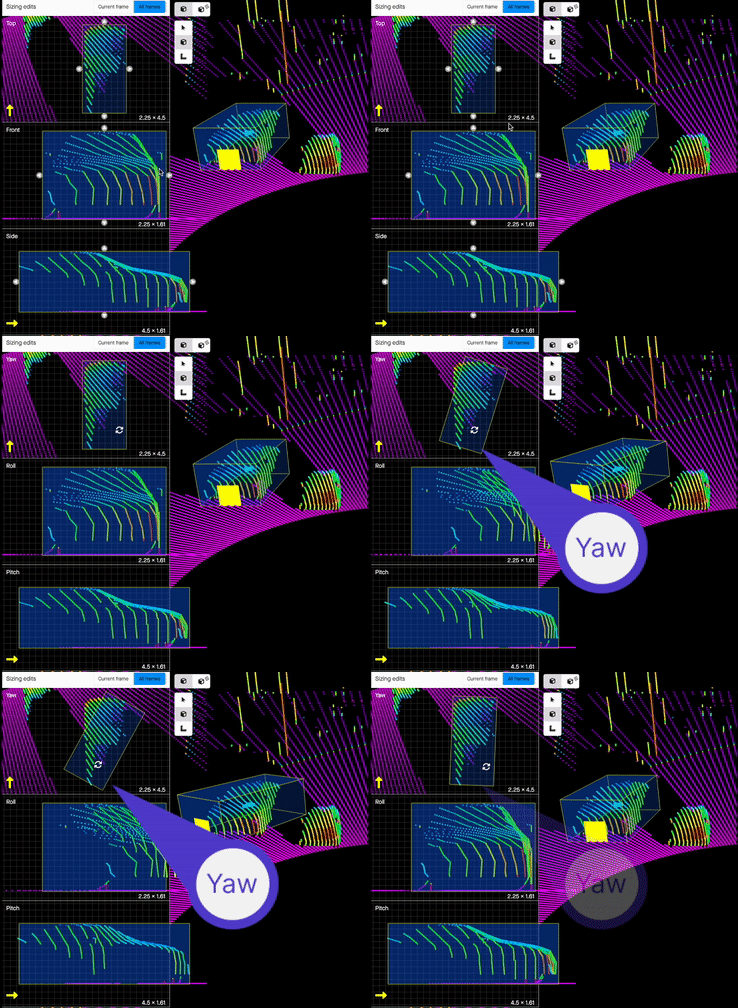
Direction is the roll, pitch, and yaw of the cuboid. Using direction, it is easy to determine any faces of interest (such as the front of a cuboid that may represent the front of a vehicle).
Roll
 |
 |
Pitch
 |
 |
Yaw
 |
 |
Orthographic Shpes or Polylines
This section provides an overview of key features related to orthographic shapes and projections in both 3D and 2D environments. These tools are designed to enhance spatial accuracy and interaction within complex visual data.
|
What is an orthographic shape? An orthographic shape is a shape drawn in a 2D orthographic view, which allows for annotations using 2D tools. This view enables annotations directly on the 3D point cloud, seen from a top-down perspective. These shapes can be either polylines or polygons, are visible in the 3D environment, and are grounded to the surface. |
 |
Viewing Orthographic Shapes in 3D and 2D
Orthographic shapes can be displayed within both the 3D environment and 2D video views, allowing users to inspect shapes from various perspectives. Shapes positioned on the ground are clearly distinguishable, aiding spatial orientation.

Selection of orthographic shapes
Polyshapes within the 3D world can be selected directly by clicking, allowing for intuitive interaction and adjustments within the 3D space. This feature simplifies the selection process, enabling efficient navigation and editing.

2D Visualization of orthographic shapes
Orthographic shapes can be visualized on 2D images, allowing for easy identification and verification on a 2D plane. This feature enables cross-referencing between 2D and 3D views, enhancing spatial awareness and accuracy.
Additionally, when projections are enabled, the same shapes can be visually represented in 2D output. With camera calibration and the 3D shape visibility toggle enabled, you can view the shapes projected onto the 2D image for a consistent perspective across dimensions.

Auto-Grounding and 3D Visualization
Orthographic shapes are automatically aligned to the ground and visualized within the 3D environment, including all sub-points. This grounding capability is particularly useful for polylines, which help identify ground surfaces, enabling accurate placement of points for features like road edges or lane markings using intensity values.
This feature also allows users to verify the appropriateness of grounding, both through 2D video and within the 3D space. In cases where a shape lacks adequate ground to anchor, the grounding may appear incomplete. By advancing to a future frame where more ground surface is available, users can insert a keyframe to adjust the shape’s alignment. This enables immediate visual inspection of subpoints to confirm that they are correctly grounded across frames.

Fused Annotation
Fused Annotations are designed to enhance 2D and 3D Sensor Fusion workflows, allowing you to track key shape properties consistently across all annotations. With Fused Annotations, Sama provides a streamlined way to apply and view attribute details across both 3D and 2D workspaces, enriching the annotation experience and improving data consistency.

Key Benefits of Fused Annotations
-
Unified Annotation Experience
With Fused Annotations, you can set shape labels and attributes across any output—3D or 2D. When enabled, the attribute details linked to a shape in one view are reflected across all outputs, ensuring comprehensive tracking of essential details throughout your annotation workspace. -
Seamless Integration of 3D Cuboids and 2D Rectangles
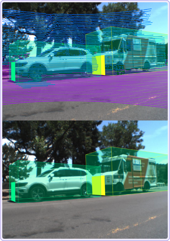
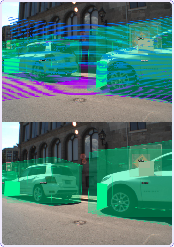
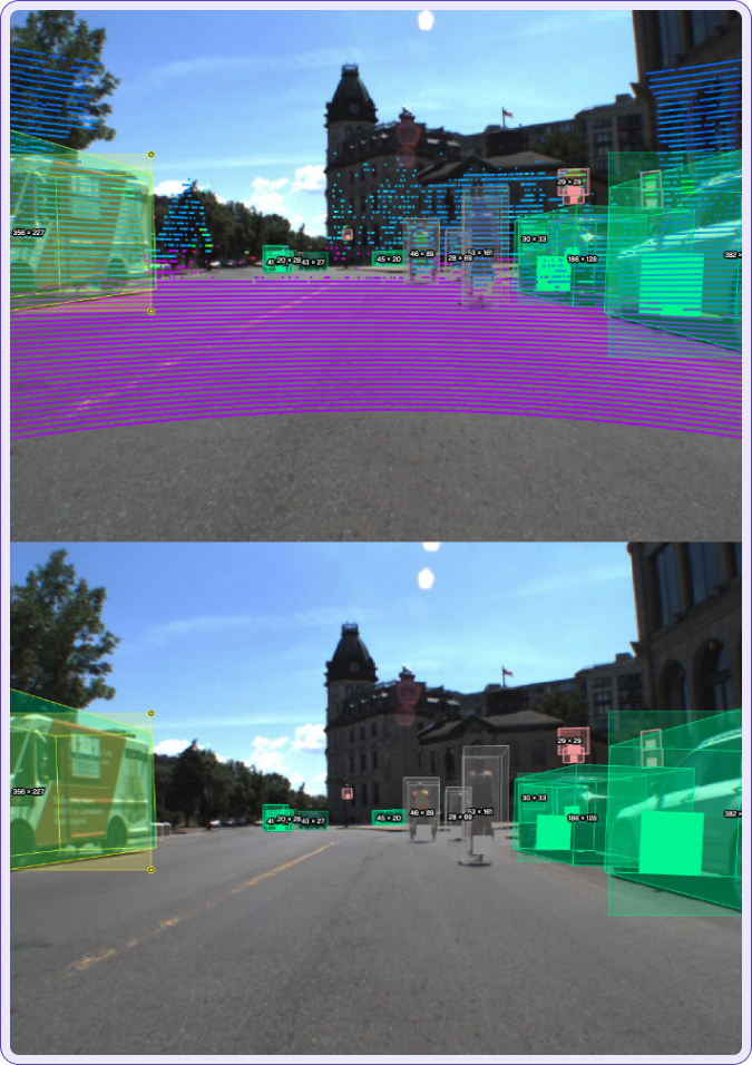
In a single Sensor Fusion workspace, fused annotations unify 3D and 2D annotations, allowing smooth transitions between dimensions. For instance, once you create a 3D cuboid, you can generate a 2D rectangle from the projected “phantom” cuboid, ensuring that annotations remain visually and contextually aligned. -
Increased Precision with Nested Attributes
Fused Annotations bring added precision by letting you apply both consistent, shared attributes and more specific shape-level attributes. This dual approach helps distinguish universal shape attributes from those specific to a single view, creating a more refined annotation process.
JSON Representation of Camera Outputs
This section provides a detailed JSON representation of the annotation outputs for each camera view—center, right, left, and scene.
Left Camera
Right Camera
Center Camera
|
Keyboard shortcuts

